


±0.1 mm Counts: The Hidden Cost of Inaccurate Strip Width Measurement in Metal Rolling
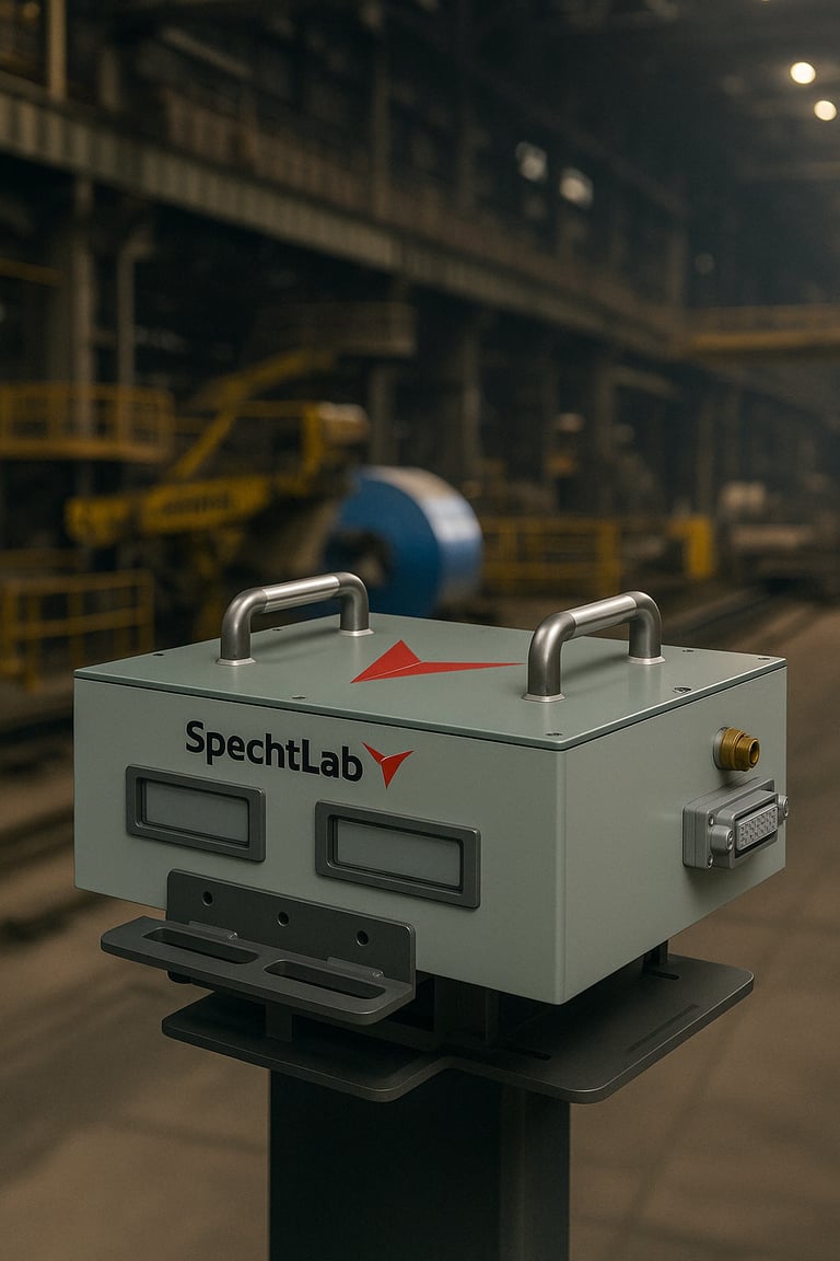
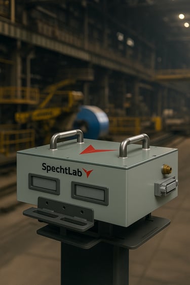
Non-Contact Strip Width Measurement System ±0.1mm | SpechtLab WG Series
3/25/20264 min read
±0.1 mm Counts: The Hidden Cost of Inaccurate Strip Width Measurement in Metal Rolling
How stereoscopic dual-camera technology achieves consistent width accuracy in the most demanding mill environments
By SpechtLab Editorial
Strip width is, on the face of it, a simple measurement. It is the distance between two edges. And yet the strip of steel or aluminium that delivers revenue — that converts raw material cost into customer value — is a strip measured not once but continuously, not statically but at speeds exceeding 1,200 metres per minute, not in a calibration lab but in an environment vibrating with rolling forces, saturated with mill scale, and subject to strip bounce that can move the material 30 mm vertically between camera frames.
Under those conditions, a width gauge that cannot cope with bounce will report systematic bias. A gauge that drifts with temperature will require frequent recalibration. A gauge that cannot interface with the mill's Level-2 automation will remain an island of data with no ability to drive the closed-loop width control that actually reduces edge trim loss. These are not edge cases — they are the reality of production measurement in a rolling mill.
The Physics and Economics of Width Variation
Width variation in metal rolling originates from multiple sources: lateral spread variation due to roll force changes, edge wave from temperature gradient across the strip width, and the mechanical bounce imposed by guide and tension fluctuations. The consequences distribute across three cost categories.
Edge trim loss is the most direct. A mill rolling aluminium alloy sheet to a nominal 1,250 mm width with a ±1.5 mm actual width control capability trims to 1,247 mm — discarding 3 mm of material at each edge to guarantee minimum width. On a 100,000 tonne annual output, those 3 mm represent approximately 480 tonnes of trim that was manufactured but not sold. At €2,200/tonne for 5xxx series alloy, that is €1,056,000 in trim scrap annually — directly attributable to width measurement and control inadequacy.
Customer claims represent the second category. Width under-specification shipments generate immediate claims from automotive and construction customers, typically at 2–5× the mill's margin on the coil. Over-specification shipments represent material given away for free.
WG Series: Stereoscopic Width Measurement Architecture
The WG Series width gauge resolves both the bounce and the environment challenges through stereoscopic dual-camera geometry. Two cameras, positioned above the strip at a known baseline separation and viewing angle, triangulate the three-dimensional position of each strip edge in every frame. Because the triangulation uses the relative position of both cameras rather than the absolute height of the strip, vertical movement of the strip — bounce — does not introduce width measurement error.
This is the defining technical advantage of the WG Series over single-camera or laser-line width gauges, which introduce width measurement error proportional to height deviation of the strip from their calibration plane. In a cold rolling mill with ±15 mm of strip bounce, a conventional single-point gauge introduces ±0.4–0.8 mm of width bias error. The WG Series eliminates this error class entirely.
The optical measurement operates in the near-infrared to suppress ambient light interference from mill luminaires and emissivity variation from the strip surface. The illumination unit is a high-power NIR LED array with strobe synchronisation — compatible with the SpechtLab BL Series trigger architecture for integrated installations.
Closed-Loop Width Control Integration
Width measurement has commercial value only when it drives action. The WG Series is designed as a width control actuator interface, not merely a measurement instrument. The system outputs width data over OPC-UA at 20 Hz, with configurable alarm thresholds and automated hold signals that can be wired directly to the mill's main drive control panel.
For edger-equipped hot rolling mills, the WG Series OPC-UA output interfaces directly to the edger position controller, enabling closed-loop width control with a measurement-to-actuation latency of under 100 ms. The system includes width trend visualisation and I-Term integration for steady-state width offset correction.
Slitting line applications benefit from per-slit-strip width reporting — the WG Series can measure up to eight individual slit strips simultaneously, with per-strip width statistics logged against the slit order number for customer certificate generation.
Implementation and ROI
A medium-sized cold rolling mill operating at ±1.0 mm width control (3σ) and trimming 5 mm to guarantee minimum width can reduce trim allowance to 1.5 mm after WG Series installation, which typically tightens width control to ±0.4 mm (3σ) through closed-loop edger control. On 80,000 tonnes annual output of aluminium sheet at €2,000/tonne, the 3.5 mm trim reduction saves approximately 280 tonnes, worth €560,000 per year. Typical payback period: 4–8 months.
For slitting centres, the primary ROI driver is customer claim reduction. A slit centre shipping ±0.3 mm width tolerance with a manual caliper measurement and sampling rate of 5% will miss 95% of width exceedances. WG Series 100% measurement eliminates virtually all width-related claims, typically representing €100,000–€300,000 in annual claim avoidance for a mid-size operation.
Frequently Asked Questions
What is the maximum measurement range?
The standard WG Series covers strips from 200 mm to 2,500 mm width. Extended-range configurations to 4,000 mm are available for wide-strip plate mills.
Does the system work on hot (glowing) material?
Yes. The near-infrared optical design and radiometric-independent edge detection algorithm allow accurate width measurement on hot strips up to 900°C surface temperature without calibration adjustment.
What installation downtime is required?
Standard installation requires 8–12 hours of mill downtime for mechanical mounting and alignment. Software commissioning and closed-loop calibration are completed during the first production run without stopping the mill.
How is the system calibrated?
A certified width reference bar is used for initial calibration. In-process calibration verification uses the strip edge position reproducibility check, automated daily at shift start.
Every millimetre of unnecessary trim margin is money manufactured but not sold. The WG Series turns width measurement from a quality compliance function into a direct cost reduction lever. Contact SpechtLab to model the specific trim-loss reduction and claim-avoidance opportunity for your production line.
Ready to see SpechtLab technology on your production line?
Contact us at www.spechtlab.com · info@spechtlab.com
AI - Powered Measuring Systems
info@spechtlab.com
© 2024. All rights reserved.